From The Desk of ABS President - Jim Batson
The 2012 American Bladesmith Society's All Forged Blade EXPO is the premier show for hand forged blades. From utility blades, to the finest forged and crafted art knives, the ABS EXPO has something for everyone. The show will be held in San Antonio, Texas, January 27 – 29, 2012 the home of the Alamo.See some of the world's finest forged knives showcased in a unique and informative format for the enjoyment of the forged blade collector/enthusiast by American Bladesmith Society Mastersmiths and Journeyman Smiths.
Dan Cassidy has set up an Expo Photo Gallery so that the makers can exhibit their knives prior to the show, so that collectors may have a sneak preview of these works of art. I have asked the table holders to make knives especially for this show and to photograph them. Please post your photos in the ABS Exposition Gallery of the ABS Forum and ABS Webmaster Dan Cassidy will be available to assist you. Also post your knife photos on other knife forums so that prospective buyers may have a sneak preview to what they will see at San Antonio.
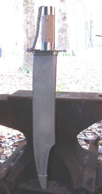
14 inch Thomas Wells Antique Bowie Progress Report.
To see previous posting,Click:Jim Batson on ABS Expo
BLADE
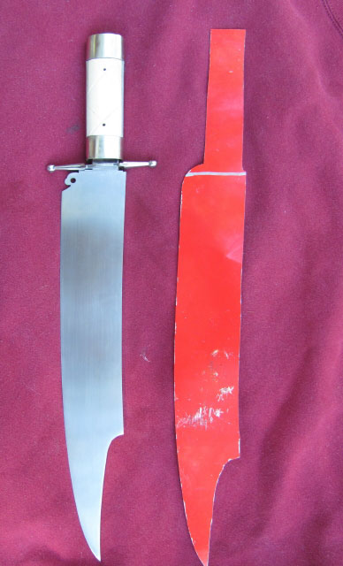
A full scale pattern was made of aluminum from a tracing of the original Bowie. The blade as it was being forged could be laid on the pattern hot as an aide to forge the blade to shape. The steel in this blade was forged from a large coil spring from a rail car.
(Photo 1)
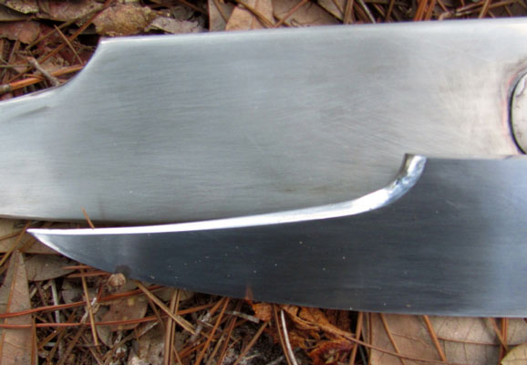
The blade was ground, set up for the guard, Spanish Notch filed , heat treated and finish ground. The maximum blade thickness is .355 inches at the hilt and .250 inches at the clip. The clip was ground and hand finished on one side of the blade as was the original.
(Photo 2)
The large tang was used to give the knife a better balance and stronger handle. The tang is tapered from guard aft and from the top down. The pin holes were drilled in the tang.
GUARD
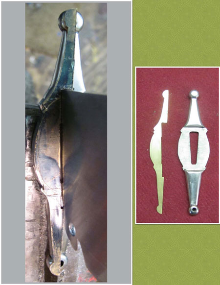
A brass 1/2 template was fabricated to the shape of the guard which fit snuggly on the blade.
(Photos 3a & 3b)
The guard was hand filed from a 1/4 inch thick piece of cupro nickel 715 , hand finished and polished. Cupro nickel 715 is 30% nickel and 70% copper and is more corrosion resistant than nickel silver which has only 18% nickel.
HANDLE CONSTRUCTION
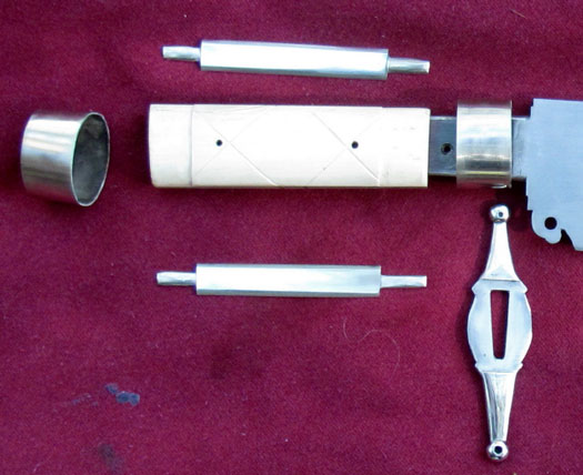
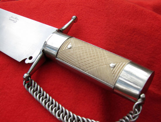
Photo 4 is the end view of the handle that shows the basic handle construction.
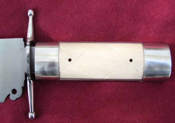
Photo 5 is the handle
and Photo 6 is an exploded view of the handle showing all its components.
The handle was fabricated by wrapping the tang with Teflon tape. A piece of tin .007 inches thick was wrapped around the tang and drilled for the pin holes. Two pieces of Mastodon Tusk were shaped into a trapezoidal cross-section to fit against the tin liner. Holes were drilled in the Mastodon handle scales. The scales were shaped a little over size in the plan view. These scales were super glued with gel to the tin liner using pins to align the holes and a rubber band made of an inner tube as a clamp. The assembly was removed from the tang and a dam was made at each end of the handle with masking tape. The voids at the top and bottom of the handle above and below the tang were filled with JB Weld. The handle was ground to final shape in a rectangular cross-section with each scale being of equal thickness.
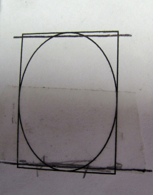
The handle is a little larger at the pommel than at the guard. I went to Microsoft Word and made a drawing of the rectangular cross-sections at the front and back of the handle. I drew an ellipse in the rectangles and printed them out.
(Photo 7)
I then cut out the rectangles and pasted them on the front and back of the handle. The handle was shaped with new belts from 36 grit and 80 grit on the flat platen by holding the handle vertically against the platen. The handle was hand finished to 600 grit.
The front of the handle was taped around the handle the required distance from the end as a guide for the front ferrule. A course file was used to recess the handle .032 inches. The pommel was done the same way. A piece of cardboard .032 inches thick was used to measure the circumference of the ferrule. A rectangular of dead soft German silver .032 inch thick was sawed out a little oversize. The handle was used to form the ferrule with the solder joint at the bottom. The joint was overlapped. Both ends were sawed into with a jeweler saw while held in a vise to obtain a straight joint. The ferrule was opened wide enough to allow an eight inch mill bastard file to be used to file the ends. The file is held in the vise with the face up and both ends are filed at the same time by pulling the ends along the top and bottom faces of the file with a slight pressure. The ferrule and pommel ferrule are wired up, fluxed and hard soldered. The ferrule is suspended by the top; the solder is applied to the inside and the heat to the bottom or outside. When the solder appears on the outside, it is done.
The pommel ferrule was wired to an oversize .070 inch thick plate on one end. It was fluxed and pieces of medium hard solder were laid around the joint on the inside and heated from the outside.
The top and bottom straps were made from 1/2 inch wide by .070 inch thick German silver. The bevels were ground and hand finished on each side. The ends were hand file to fit under the front ferrule and pommel cap.
CHAIN KNUCKLE BOW
After some experimenting, I found that the original chain was called a rope chain that was twisted into a flat plane.
(Photos 8a, b & c for construction details)
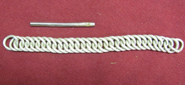
Eleven gauge (.088 inch diameter) fine silver wire was wrapped around a 3/8 inch diameter rod by hand. Thirty-six turns were made. Over 4 feet of wire was used. This coil was removed from the rod, fluxed and heated to a dull red, about 1250 degrees F., for about 30 seconds allowed to cool to a black heat and quenched in water. One loop was silver soldered with medium hard solder. The chain was constructed and soldered one loop at a time. After using about 10 loops, the chain was twisted flat to insure good solder joints, The chain was completed with 31 loops. A .093 inch internal diameter tube was constructed to make the hinge attachment to the pommel cap. The chain and tube are pictured in Photo 9 below.
METAL SHEATH
(Photo 10)
The all metal sheath was constructed of .032 inch thick German silver sheet metal. After the blade was finished a pattern was made of a piece of oak about 3/4 inches thick. The pattern was made oversize to allow for the liner which is about .040 inch thick. Also make the pattern about 3 inches longer than the blade, the edges were rounded slightly. The sides were cut out of the sheet approximately 3/8 inches wider than the pattern on top and bottom. The tip was notched to allow for the bend. The sheet metal I had was in an as rolled state which was hard. I had to anneal the edges that were to be bent.
To shape the sides, place the sides between the pattern and a steel backing in the vice and bend the edges over with a small hammer only hitting the edge in a bending motion. You will have to reset in the vise several times. Take thickness measurements along top and bottom of the blade. Grind the edges of the sides to the require thickness, making sure you have allowed for the metal thickness, the liner thickness and 1/2 the width of the blade. Lay the side flat on the table and measure the height with the depth gage on the back of a veneer caliper.
Once the left and right side are made, flux the inside of each at the joint. Wire the two sides together with black wire at half inch increments. Flux the outside, use a metal spring clamp on a fire brick to present a joint in the up position to be soldered. Solder both sides with medium silver solder. I use a turbo torch and wire solder.
Cut and pull the black wire off. I grind the extra solder off with about 80 grit. I use 120 grit to start the finish grinding on the sheath. It is easier to get the 120 grit scratches out than the 80 grit. You want to polish to 400 grit on a wheel. I use a 10 inch smooth 40 diameter wheel with a 3 inch drive pulley.
The sheath should be pickled to clean the inside. The tip and throat pieces were fitted, constructed and soldered with medium solder. These pieces were then soldered to the sheath body with easy easy solder. The belt loop was formed and tinned with soft 4% silver solder. It was then soldered to the sheath.
WHAT'S LEFT
1. Finish chain and pommel cap attachment with hinge. Polish chain in tumbler.
2. Layout incise carving pattern on handle and carve.
3. Assemble and finish knife.
4. Layout engraving pattern on sheath and engrave.
5. Line the sheath
James Batson, Master Smith
[email="[email protected]"][email protected][/email]
Very interesting knife! Thanks for taking the time to show us the details of it's construction. I look forward to seeing the finished product.
It's great to see a WIP from Dr. Batson! I look forward to seeing the completed knife!
Second Progress Report
The 14 inch Thomas Wells Antique Bowie is finished except for engraving T. Wells and Nashville on the handle mountings.
CHAIN & POMMEL CAP HINGE
Chain Hinge photo
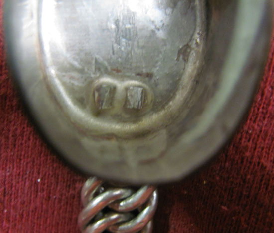
The first loop of the chain was sawed with a jewelers saw so that the first and second loop would butt against the hinge tube. The tube and chain were silver soldered together. The center of the tube and joint were sawed out to accept the hinge post that would be attached to the pommel cap. The chain was then polished by tumbling with stainless steel shot. A 3/32 inch diameter hole was drilled in square peg. The leg of the hinge peg was filed into an 1/8 inch diameter and split lengthwise. A hole was drilled in the pommel cap, the peg inserted, and riveted as a split rivet. The legs of the peg were silver soldered to the inside of the cap to keep the hinge peg from rotating.
solder joint photo
The chain was attached to the pommel cap with a 3/32 diameter monel pin. The ends of the pin were upset with a small ball peen hammer.
HANDLE INCISE CARVING
The photo of the original handle was enlarged to determine the design, the size of the spacing, etc. There were three basic spacings, 8, 12 and 16 lines per inch. The lines were laid out with Dembart checkering cutters. The 16 lines per inch was standard but the 8 and 12 were done with a 16 and 24 lines per inch skip cutters which ends up being 8 and 12 lines per inch.
The cuts were finished with a fine toothed 90 degree cutter. The center square panels were deeply cut as were the original. The cuts were cleaned with a tooth brush.
HANDLE ASSEMBLY
Thirty minute epoxy was used to assemble the handle components, pommel cap, top & bottom strap and ferrule, to the handle body. The handle was then slid onto the blade before the guard was attached. The blade was positioned in vice with soft jaws. The top and bottom straps were aligned with the blade with a 2 foot straight edge positioned against the blade and over the straps.
The excess epoxy was removed by wiping with petroleum jelly and paper towels. The handle components were clamped together with a large inner tube rubber band, fore and aft and all around.
GUARD TO BLADE
My guards are made with an interference fit to the tang by hand filing. The back of the blade, tang and inside of the guard were cleaned with alcohol and fluxed. Heat absorbing paste was applied to the cutting edge near the guard. The guard was driven down flush with the back of the blade, insuring that the guard is against and square to the blade.
The blade was held vertically with the tang up. Four percent silver solder was flatten and cleaned. Four small snippets were positioned around the tang. Heat was applied to the tang above the guard to preheat. A soft heat was applied to the blade and guard from the bottom to pull the melted solder down to the front of the guard. When the flux turns black is hot enough. The excess solder can be removed from the back of the guard with an acid brush. A wet rag was used to cool the joint by applying around the guard. The flux must be cleaned very good with liquid dish soap. Clean with WD 40 and oil.
The solder joint at the front of the guard was cleaned up with an end of a brass rod sharpened into a needle point. The guard is polished with 500 grit paper and lightly buffed with an 1/4 by 8 inch buff loosely fitted to a 1/4 HP table grinder. If the blade catches the buff, you want the buff to stop rotating and not pull the blade from your hand. The buffer is the most dangerous piece of equipment in your shop. I use white lightening compound.
BLADE FINISH
The blade is clamped to a 2 X 2 inch board with a notched sawed out to accept the guard so the the blade will lay flat on the board. The tip of the blade should not project past the board for safety. I put scotch tape on the front of the guard to protect it from being scratched during the blade finishing. I also put a paper towel under the blade. The blade has previously been finished to 400 grit by hand. All you are doing now is the finishing touches. I use a 1/8th inch thick piece steel about 1/2 inch wide and 6 inches long. A 45 degree bevel has been ground on one end and along one side. You can clean up the solder joint with tool and fine sandpaper without damaging the guard face.
I use a rubber backed rubbing stick about 1 to 1 1/2 inch wide, 3/8 inches thick and 8 inches long to finish the blade with even strokes up to 500 grit. I then use a micro fine pad from Rio Grande to finish the blade.
FITTING HANDLE TO BLADE
The ferrule on the front of the handle was left too long. The pin holes in the tang will not line up with the holes in the handle because of this extra length. The extra length is ground off on a flat platen with an 80 grit belt while fitting the ferrule against the guard. Two 3/32 inch diameter over length pins are tapered. The goal is to have a good fit of the handle against the guard with the hole locations of the tang and handle offset so that when the pins are driven in the handle is force against the guard. The final fitting is done by hand sanding the end of the handle on 80 grit paper mounted on a flat surface. This is done by putting down pressure on the area where the metal is to be remove while sanding.
The blade is protected by covered with paper and taping with masking tape. The handle is taped with masking tape to keep the epoxy out of the incised carving. Holes need to be punched in the pin holes and covered with small pieces of tape.
Thirty minute epoxy was used to secure the handle to the tang. The tang was degreased with alcohol. The epoxy was heated with a hair dryer so that it would run easily.
It was mixed on a piece of cardboard that was creased into a V shape or trough. The epoxy was poured done one side of the tang hole so that no air bubbles were trapped. The tang was shoved into the hole and more epoxy was poured in until there was enough epoxy to fill the hole with the handle against the guard. Epoxy will be leaking out of the pin holes. I use petroleum jelly and paper towels to remove the excess epoxy. Dip the pins in the petroleum jelly and drive into the handle and tang holes forcing the handle against the guard. Check to make sure that there is a good handle to guard fit.
The tape can be removed from the handle before the 30 minutes are up. If there are any excess epoxy, now is the time to remove it before it gets hard. Petroleum jelly, paper towels and maybe a tooth brush will be needed.
Once the epoxy has hardened the pin holes are enlarged to 1/8 inch diameter by drilling through the tang from both directions to insure that the hole in the Mastodon stays round on both sides. A 1/8 inch round German silver pin stock is heated to a red color and quenched in water to anneal. The inside edges of the pin holes are tapered slightly with a wood spade bit. The pins are left about a diameter and a half too long on each side. The ends are domed and polished on a 400 grit belt. The pins are upset and domed with a small polished ball peen hammer against a polished anvil face. Once the ends have been upset, put a piece of masking tape over the pin and Mastodon to protect the carving while forming the domed heads. Be careful and be patient with light taps. You do not want to stress the Mastodon, so that it will crack later when subjected to different environments.
Have you wife inspect the knife for Quality Assurance.
ENGRAVING THE SHEATH
The original sheath was engraved with wavy lines and festoons. The bright cut script lettering was cut probably with a palm held flat graver. The same graver was probably used to wiggle cut the wavy lines and festoons on both sides of the coin silver sheath. Wiggle cutting is an old method of engraving by which the engraver places the flat chisel cutting edge against the metal at an angle of about 45 degrees to the sheath and walks it back and forth from side to side like a man walking obtaining a zigzag pattern along the line. By enlarging the photographs of the original engraving one can determine the method of engraving and by scaling can determine the size of the tool.
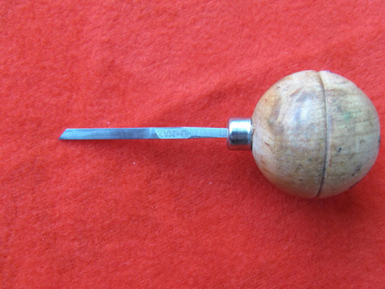
I estimated the flat engraver to be about ,040 inches wide. I took a piece of 1/8 inch square momax tool steel and ground it to .045 inch thick and ground a 45 degree face without a heel. Mounted it on a wooden ball.
Engraver photo.
There are some wiggle examples in the Wiggle photo.
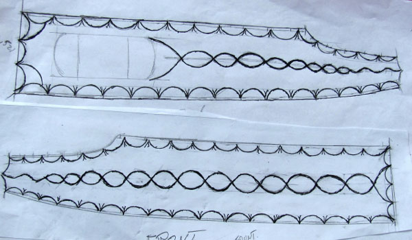
The wavy line and festoon patterns were drawn for the front and back in the pattern photo. The charm of the original engravings were not from being exact geometric figures but from the fact that you could tell that they were hand drawn without regiment.
pattern photo
I filled the sheath with sand and mounted it onto a wood board with hot glue in preparation to being engraved.
To me this knife and sheath is truly a product of art and craft of the the times, Folk Art of early Americana.
Things to do.
1. Transfer engraving design to Sheath and Engrave
2. Letter engraved T Wells and Nashville to Handle and sheath
3. Line the sheath
James Batson, Master Smith
[email="[email protected]"][email protected][/email]
An excellent description of the work!!
Have your wife inspect the knife for Quality Assurance.
THERE'S a key bit of advice!! <img src=' http://www.americanbladesmith.com/ipboard/public/style_emoticons//smile.gi f' class='bbc_emoticon' alt=':)' />
Great knife, Dr. Jim. Thank you for the WIP, it answers a lot of questions.
I definitely have to agree with having your wife inspect the knife. I just love the "What is this" question. Then it is back out to the shop.
Brion
Brion Tomberlin
Anvil Top Custom Knives
ABS Mastersmith
Third and Final Report
The 14 inch Thomas Wells Antique Bowie and sheath are finished, The knife weighs 1 pound 12.4 ounces and in the sheath weighs 2 pounds 7.2 ounces.
Wiggle Engraving Sheath
The sheath was first filled with sand to strengthen the sheet metal to resist the force of the engraver. The sheath throat was sealed with masking tape.
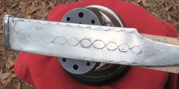
The sheath was then hot glue to a wooden block so that it could be mounted on an engraving ball to be engraved. See side view and Mounted engraved Sheath photos.
The full scale hand drawn sheath engraving pattern was Xeroxed. This copy was cut out and taped to the sheath. The Xeroxed ink or toner was transferred to the sheath by wetting with acetone and drying by pressing a folded paper towel against the back of the pattern.The sheath was wiggled engraved.
The sheath was removed from the wooden block by spraying with alcohol on the hot glue joint. The front of the sheath was engraved next by wiggle engraving as seen in photo.
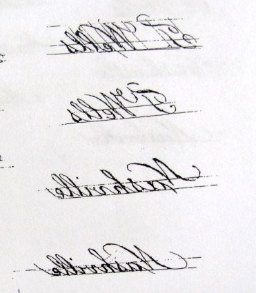
The original T. Wells script sheath engraving picture was blown up over size. The out line of the letters were traced over on onion skin paper. The letters were filled in and darkened with black ink. This copy of the original engraving was reduced to the original size and a mirror image was made and Xeroxed in preparation for transferring to the metal sheath by the acetone method. See T Wells mirror image.
The script letters were cut with a 105 degree square engrave with the aid of a hammer.
The sand was remover with the aid of water. The sheath was dried out in an oven at 180 degrees for 30 minutes. Stiff Moroccan leather .025 inches thick was used to line the sheath. A strip of leather about 3/4 of an inch wide and 3/4 th the sheath length was creased into a vee and epoxy to the inside of the sheath for the cutting edge to ride along. The throat of the sheath was lined with the around the inside circumference for about 5 inches in length.
the end
James Batson, Master Smith
[email="[email protected]"][email protected][/email]
Nice work Dr. Jim!
A great work in progress report! I hope to see more like this in the future.
I know it takes alot of time to post a project like this,and we want you to know it is appreciated!
Thank You!
Russell
Jim, thanks so much for the detailed description of how you approached each aspect of building this knife -- a very complex one. I particularly enjoyed learning how you made and attached the chain guard -- that's a feature we almost never see on antique bowies and I guess that I've never given much thought to them.
Maybe I can add a little background information on the original. The first time I encountered this knife was in a Butterfield's arms auction catalog, not one of the big bowie knife auctions but one of their regular arms auctions (just looked it up, it was sale #5241A, in 1993). I can remember thinking that the knife was so strange it surely couldn't be authentic... the sword-like chain guard, the offset handle paired with a full guard, the unusual clip, unusual checkering, so on and so forth. What a combination, plus a spanish notch and an inscription? Too good to be true, right?
I finally got to handle it in 2000, at an ABKA meeting... and instantly changed my mind. Highly unusual, yes... but in person it was easy to see that it was authentic. Furthermore, it's my understanding that the current owner's research has turned up a 19th century reference to the knife in the probate records relating to Thomas Wells (as I remember it, Wells specified what should be done with "my large knife"). Pretty cool, huh?
The fellow who made it was obviously a very skilled craftsman capable of forging steel, working with silver in sheet and wire form, checkering ivory, etc... a very diverse set of skills. But I doubt that knifemaking was his main trade; if it were we'd expect to see other knives exhibiting combinations of this knife's features. And before anybody says "Samuel Bell"... IMHO there's nothing here to suggest that this is Samuel Bell's work. Someone of the same period with a similar skill set, yes!
A really fine knife -- very large, very unusual, and probably quite early, and it serves as a good example of why we should 'never say never' with regard to antique knives.
Mark Zalesky
Jim,
What a beautiful knife. Thank you for the WIP! I was able learn many new things...Thank you!
How was the knife received at the show? I can only imagine the difference of seeing it in person versus photos.
Thanks again for posting.
Rick
Just tuned in to this WIP
Jim this is an amazing knife and sheath. Its hard to believe how complex the build is and you documented it completely. Thank You for doing this. Very much appreciated.
Bruce Bump, Master Smith
Full Time Knife and Pistol Smith. Living the Dream.

