This month's topic is how to design and build a propane forge. A lot of us have made our own propane forges and blowers. Post up pictures of your forge. Tell us what materials you used and how the forge and/or blower was constructed. Where did you purchase the materials for building your forge? Your design for a forge work rest is also good information.
I will be following this thread very closely as I just got a large propane tank with a bad stem. I plan on building a vertical blown gas forge out of it.
There is an excellent video on how to build a propane forge by Journeyman Smith Dan Hockensmith on the ABS YouTube Channel.
[media] http://youtube.com/watch?v=pgtUfbfQBw0 [/media]
Dan Cassidy
Journeyman Smith
Send an email to Dan

Dan,
Thank you. This gives me a good idea on how to do my forge body. Will be following the thread looking for information on a blower based burner. I have been told that the type of burner works best on larger forges.
Regards,
George
I don't have a lot of good things to add as far as building a great gas forge. That being said, I decided maybe it'd be worth posting what I ended up making a couple years ago and sharing some things that didn't work so great. Maybe that'll help someone be a little more successful on their build...
I used an old, horizontal propane tank from a junkyard that a friend helped me cut down. I bought some weldable hinges for each end, so I could swing the doors up out of the way. That actually turned out to be a decent thing. While I don't open them a lot, it's helpful for a few different processes, as well as replacing/repairing anything on the inside.
And here was one of the major design flaws (other than the forge body being too big). For some unknown reason, I decided it would be a good plan to place the burners at an angle, instead of straight down on my work, which I'd seen on some other forges. All I did was end up pointing the flames to one corner of the inside. I think I remember figuring that the work material not being directly in the flame would be better...? I keep wishing I had just made them enter the top about horizontal so I got the swirling motion and hopefully then, a more even heat. Also, the burners were put too close together.
I put thin firebrick in the bottom for a solid bottom and lined from there with 1" kaowool. I bought some dry refractory powder from the local pottery supply place and coated it all. Then I put a second set of thin firebricks over the base which brought the interior base up to the same level as the opening in the doorways we cut. I figured the bricks would last a bit longer and the second layer would be very easy to replace over time.
Here you can see some of the black from forge welding-more on that in a minute...
I really wanted to be able to forge weld and knew I might not be able to based on my design (and it being a venturi, not blown). I got some pyrometric cones from the same pottery place (#10) and cranked up the psi. The cones, which should begin melting and bending over at 2345 degrees, just wouldn't... So, I got some ITC 100 and coated the interior with that. I have to crank the psi up to get to temp, but I can reach forge welding temps now without issue.
More to come...
Jeremy Lindley, Apprentice Smith
Now to the burners. I used black pipe for all the fittings and chose to weld collars to the forge body to hold the burner tubes. A second collar on the tubes with set screws would let me adjust how far in the ends went. I also thought this would be good because I could just pull the burners out when not in use. When I first started, I had a cramped little section of the garage that I moved everything into after each use, so making stuff easy to take apart was important at the time. The burner portion itself is a black pipe nipple, capped at one end and a reducer on the other for the gas. I drilled a small hole in each nipple, then we welded a nut over the hole that an .035 mig tip screwed nicely into. The nipple was then welded to the bell reducer.
I got a section of hose that I attached fittings to for a "T", then two hoses from there into valves and quick release fittings to pipe nipples. I will occasionally get fluttering of one of the burners, especially if one is turned off, then I try to turn it back on. My guess is, there isn't consistent gas pressure to each burner, especially once one is turned off?
On the door openings, we welded a piece of angle iron for a "shelf". I would absolutely put a bit bigger piece of steel at the opening to help hold material. Also, I now have a larger area and mounted the forge on a pedestal. With the angle iron "legs", I'm planning on bending up some mild steel stock I have to slide into the openings and will be able to telescope in/out to help hold up rebar handles, etc.
(Don't worry, the base is welded, not just held with bailing wire...)
All in all, the forge makes steel hot enough to work and even forge weld, so I suppose that it was a success? That being said, I have a serious hankering to have a better, more efficient one. The more shops I visit, I see guys using a venturi type for a lot of general forge work and a second, blown forge for their forge welding. I'm thinking I'll likely go that route somewhere in the future. Though I can say the venturi will be a ways smaller and only 1 burner, correctly positioned this time.
Not sure that'll be helpful to anyone, but figured I'd share my experiences. I appreciate all the help I get from this site and if anyone would like to provide some suggestions on what kinds of things to fix on mine, please feel free to do so <img src=' http://www.americanbladesmith.com/ipboard/public/style_emoticons//smile.gi f' class='bbc_emoticon' alt=':)' />.
Jeremy
Jeremy Lindley, Apprentice Smith
When I started this thread, I thought that I had some decent pictures of my forge. Guess not. But, I took some today and will post them after editing. I do have information and photos of my burner assemblies.
These are photos of the burner assemblies that I build for use on my forges. The burner on the white background is made of 2 inch steel pipe, from the blower to the forge. The nozzle is just a pipe cap with a hole drilled in it. The gas inlet pipe is 1/4 in steel pipe. The gas pipe extends about 1 inch into the elbow. There is no orifice on the gas inlet pipe. All control of the gas is by the ball valve. A ball valve works okay for a large burner assembly. But, a needle valve is easier to control when used on small burners.
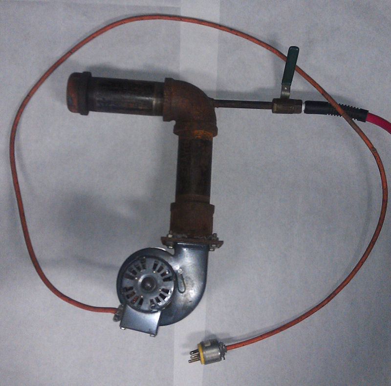

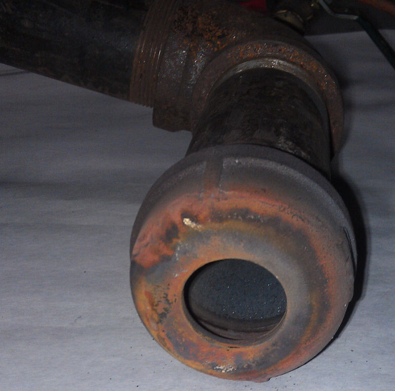
The size of the hole drilled in the pipe cap nozzle, is determined by the size of the forge that the burner assembly will be used on. The hole in the cap in the photo is 1 1/4" in diameter. This cap is installed on a large burner assembly, that is used on a forge that has about 600 cubic inches of interior space. Start with a smaller hole size in the cap and try the forge out to see how long it takes to come up to heat. If it takes too long, increase the diameter of the hole until you have enough blast to bring the forge up to temperature in a reasonable amount of time.
Air control is by a sheet steel damper over the intake of the blower.
These burners can be built with a smaller pipe diameter, depending on the size of the forge they will be used on. The burner mounted on the small forge is made of 1 1/4 inch pipe. This small burner assembly uses the same size blower.
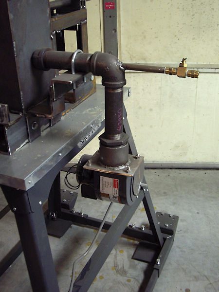
When mounting the burner assembly to the forge, the pipe cap nozzle is not inserted into the body of the forge. The nozzle just butts up against the side of the forge. The blast is sufficient to blow the flame into the forge.
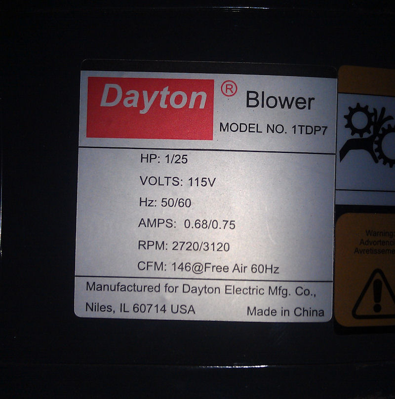
The blower that I use on these burners is a unit that puts out 146 cubic feet of air per minute. This blower is a Dayton, Model #1TDP7. I bought this unit from Grainger Industrial Supply. I added the sheet metal damper to control the air volume through the blower.
These burner assemblies are cheap, easy to build and they work great. I have been using this design for over 20 years. I have never had one of the pipe cap nozzles burn up and have never had one of the blowers quit working. Doesn't get any better than that.
I've got a bit if a dumb question... Would using a blown burner on a horizontal forge work well or not? If the burner was positioned well to swirl around the interior, would it work? I guess I've just never seen a blown burner except on a vertical forge.
Jeremy
Jeremy Lindley, Apprentice Smith
Jeremy,
Yes, I use a similar type burner on my horizontal forge.
Bob
Jeremy,
These burners work great on horizontal forges. I ran one on a horizontal for 15 years. I intend to build myself another horizontal just for blade forging and will install this type burner on it.
Thanks very much for the responses. I'm starting to wonder if I couldn't modify my current setup with a blown burner like pictured here... Would you guys suggest the burner coming in horizontally at the top of the forge? Depending on the size of pipe used, I wonder if I could cap off one of my burner holes and just butt the kind of burner shown here to the next one at a more proper angle and get decent results? Thank you both again for the advice and posting your setup, Mr. Culver.
Jeremy
Jeremy Lindley, Apprentice Smith
This is a walk around of my forge. The forge is made of castable refractory which is a lot like cement. This design has a 6" inside measurement and the hole on the other end allows for long pieces to be forged.
[media] http://www.youtube.com/watch?v=jjH1J8fstB8 [/media]
Brian
I use a burner I use is almost identical to Steve's. The main exceptions are a needle valve, to regulate the gas flow, in addition to the ball valve that is used to shut off the gas. I used 1 1/4" pipe with a big ball valve ahead of the blower to control air flow. It was simple to build and I've been using it for years without any problems.
Dale
Dale Huckabee
Journeyman Smith
dalehuckabeeknives.weebly.com
Jeremy,
I believe the thought process of most forge builders, is to put the flame opening tangent to the forge interior. This is supposedly the best way to make the flame circle the interior of the forge. I'm going to do another post on this thread, that will include a sketch of my forge design that illustrates this. I think your flame openings are sufficiently angled to be worth trying a blown burner.
I took some pictures of my forge and loaded them to the Jigs and Fixtures page of my web site. Rather than clutter this thread up with a lot of photos, I'll just post a few and you can click on the link to go to my web site and see the rest. The forge stuff is at the bottom of the page.
I never took pictures of casting a forge body. I'm learning that I should just take pictures of everything I do in the shop. I've done some sketches of the forge body design. I hope they make sense to everyone. I'm planning a forge building seminar at my shop. I'll get some photos of the actual process and add them to this thread later.
I cast my forge bodies of Mizzou Plus, castable refractory. Mizzou is not a high insulating refractory. It is primarily a structural type. Mizzou will not contain heat inside the forge. So, the forge body must be wrapped in Inswool. I wrap my forge bodies with a layer of 1 inch thick, 8 pound Inswool.
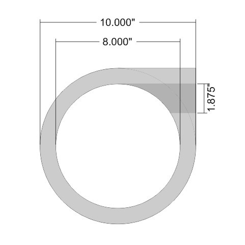
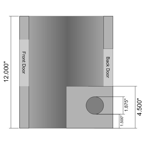
These are sketches of the cast forge body. The body is 12 inches tall and 10 inches in diameter on the outside. The interior is 8 inches in diameter. The forge body walls are approximately 1 inch thick. The top and bottom pieces of the forge are 1 inch thick plates of Mizzou Plus.
Forge Top View
Forge Right Side Cutaway
Casting one of these forge bodies is just like casting concrete. You build forms to shape it and pour the mixed refractory in. Use a stick to pack refractory in tight areas and tap the outside of the form to work out air pockets. To cast these round forges, I use the cardboard forms that are sold to cast concrete piers. You can buy these forms at Lowe's, Home Depot, etc. A bit of advice; take a tape measure to check the diameter of the forms when you go to purchase. There seems to be absolutely no quality control on these things. You will find a multitude of diameters in each given size. Make sure that you have two forms that will give you about a 1 inch thick forge body wall.
Pieces of wood were cut from 2x6 boards to block out the door openings during casting. The wood blocks were inserted through both cardboard forms. This helps to stabilize the forms and shape the door openings. When cutting the wood blocks, put a slight taper on the edges of the blocks, towards the interior of the forge. This helps with removal of the blocks from the cured refractory.
The flame opening was formed using a piece of 1 1/2 inch PVC pipe. The resulting flame opening is 1 7/8 inches in diameter. The bottom of the flame opening is 1 1/2 inches above the bottom of the forge. I cast a 4 1/2 inch tall, rectangular block around the flame opening for additional strength. This may not be necessary.
Both forge door openings are 4 inches wide. The front door is 5 inches tall. The back door is 4 inches tall. The bottom of the doors are 4 1/2 inches above the bottom of the forge.
Forges made of Mizzou WILL crack in use from thermal expansion. This has never caused a problem with my forges. The forge body has always stayed together. I've been concerned about my forges falling apart from jostling around, but I've never had that happen. My forge has been loaded in my truck and hauled back and forth to the Heartland Symposium. It's still standing. Lin will get to use it at the next Heartland.


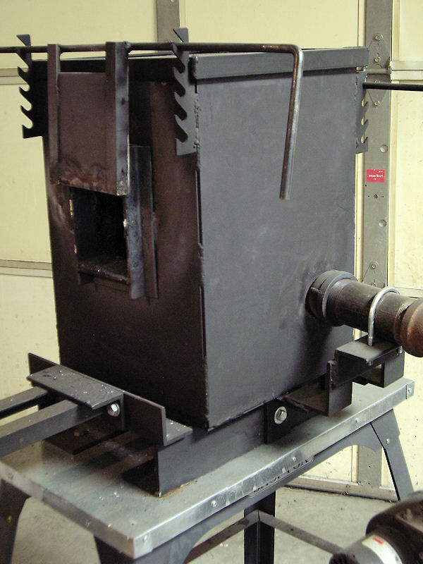
My forge has a steel casing around it. Maybe that's why it hasn't fallen apart from trucking it around. I built the steel casing primarily to facilitate installing doors on the forge. I have built and used these forges with only the Inswool overwrap. So, the casing is not necessary.
An advantage that forges cast from non-insulating Mizzou have, is that the refractory absorbs heat from the fire. So, the refractory becomes a heat sink. In a forge built of just insulating materials, the only heat energy available is from the flame. With the refractory acting as a heat sink, the steel being heated also gains heat from the hot refractory. When welding a large billet of damascus, I feel that my forge brings the steel back up to welding temperature much quicker than if it were only gaining heat from the fire. Too, the temperature of the forge is very stable and doesn’t drop significantly when a piece of cold steel is inserted. Once my forge is up to a welding heat, I can back the blast down and it will idle along all day long at welding heat. Nice and quiet. It takes my forge about 20 minutes to get up to a welding heat. So, it's probably slower to get to heat than forges of just insulating refractory. But, I know this and just plan my work around the time required by the forge.


